System Options - General
The General parameters of Designer can be set from the System Options area: the system must be restarted for them to be set as default and be applied each time a new session is started.
Access
1. Click on the File > Settings > Options icon.
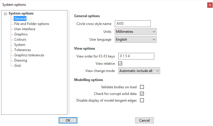
2. Select the General option from the dialog displayed and enter the required values. ![]() See image.
See image.
Parameters description
General options
|
Circle cross style name |
Allows you to set the style name for the axis of the circle. |
|
Allows you to set the measurement unit by choosing between millimetres and inches.
|
|
|
Allows you to set the language of the user interface:
|
View options
|
View order for F2-F3 keys |
Allows you to set the order of the views when you toggle between them by using the function keys F2 and F3. Enter the numbers corresponding to the position of the views into the list displayed by the Select a view dialog (see below). |
|
View relative |
Activate this option to set the current workplane as default (instead of the absolute workplane) for toggling between views using the function keys F2 and F3. |
|
View change mode |
Allow you to define the view mode during the view changes:
|
![]() Note:
Note:
The View options can also be set for the current session only by toggling between the options View ABS and View REL from the Status bar. For more details refer to Status Bar - View Management topic.
Modelling options
|
Validate bodies on load |
Activate this option to verify the geometrical validity of each single solid both when opening the VDA file and during the modelling phase.
|
|
Check for corrupt solid data |
Activate this option to check for corrupted bodies from a mathematical point of view both when opening the VDA file and during the modelling phase. When a corrupted body is detected, a warning dialog displays.
|
|
Disable display of model tangent edges |
Activate this option to hide the tangent edges of the solids. Tangent edges are typically placed between a blend face and the adjacent ones (smooth edges).
|
![]() Note: Some changes may not be implemented until the application is restarted.
Note: Some changes may not be implemented until the application is restarted.
A message to this effect is displayed in the bottom right corner to alert users.
For further information...
From the System Options area, it is also possible to set the parameters of the following options:
- File and Folder options
- User Interface
- Graphics
- Colours
- System
- Tolerances
- Graphics tolerances
- Drawing
- Grid